Integrative Simulation: Improving the Quality of Predictions.
INTEGRATIVE SIMULATION, SHORT GLASS FIBER-REINFORCED THERMOPLASTICS, UNIDIRECTIONAL FIBER ORIENTATION, MECHANICAL CHARACTERIZATION
The mechanical properties of injection molding components made of short glass fiber-reinforced thermoplastic materials are largely dependent on the process parameters in their production. The fibers contained in the polymer molten mass are aligned in the tool cavity during the injection molding process. The flow-induced distribution of the reinforcement fibers results in locally anisotropic, i.e. direction-dependent, material behavior in the components. It is therefore necessary to incorporate the manufacturing process for the design of such components with the help of Finite Element Methods (FEM simulations). The simulation chains used in this context, consisting of the simulation of the manufacturing process in injecting molding simulations and the subsequent calculation of the structural and mechanical behavior in FEM simulations, is referred to as “integrative simulation”.
Improved prediction of structural and mechanical behavior
The completed project was focused on improving the quality of predictions of various partial aspects of integrative simulation. It involved the observation, in particular, of new approaches to the determination of material characteristic values through innovative test specimens, more robust methods for the experimental analysis of valid fiber orientation data and adjusted concepts to increase the quality of the prediction of incident volume shrinkage during the manufacturing process and of the resulting component warping. The results obtained offer new possibilities for a more precise prediction of the behavior of structures made of thermoplastic materials by means of FEM simulation.
The new findings are incorporated into current project proposals at Fraunhofer LBF and are also part of two ongoing doctorates.
Tool for unidirectional test specimens
In short fiber-reinforced, injection molded thermoplastic plastic boards, the reinforcement fibers are ideally laid out in a structure made up of three layers: In both outer layers, they are aligned in the fill direction; in the middle layer diagonal to this [1]. There are negligibly few fibers in the thickness direction [2]. Additional interim layers are defined by alternative models to describe the fiber orientation structure.
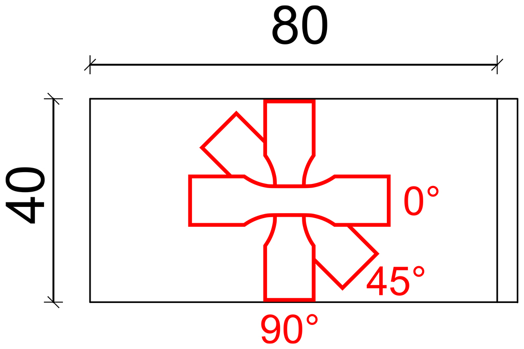
If thermal or mechanical properties are tested with these boards, the properties of the various layers overlap [1]. However, it is worth having information on the influence of each individual layer in order to clearly correlate the physical behavior and the fiber orientation. Unidirectional test specimens (UD test specimens) are therefore required. A tool for a new test board from which UD test specimens can be taken was developed at Fraunhofer LBF. One of the unique selling points of the new test board is that the UD test specimens can be removed at various angles to the injection direction. This is shown graphically for the removal angles of 0°, 45° and 90° in Figure 1. Therefore, characteristic values can be determined depending on the fiber orientation without the need to take a middle layer into account. This provides new unique possibilities for the more precise determination of e.g. thermal expansion coefficients, malfunction characteristic values under mechanical loads as well as for the validation of the model assumptions currently being applied.
Tool design for optimized characteristic value determination
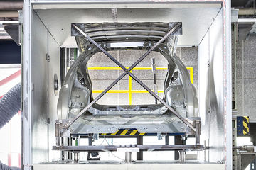
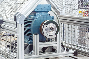
The new tool was designed as a mold which can be integrated into an existing basic tool as an insert. The basic tool contains the injection unit with its nozzle, the cooling channels and the ejector.
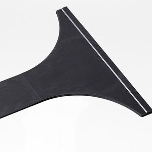
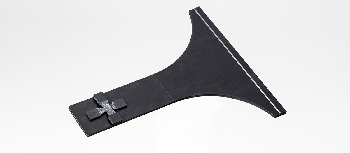
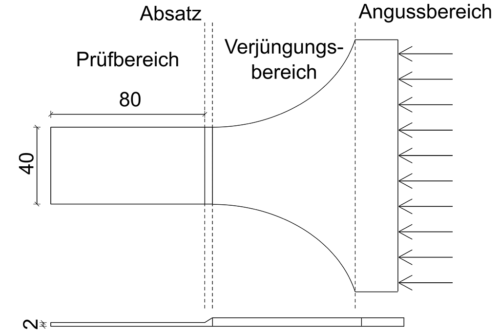
The design phase comprised an optimization of various geometric shapes in the sprue area, rejuvenation, ledge and width as well as length of the test area. The test area was designed in line with a high fiber orientation. The focus of the project was on a PBT-GF30 material. The geometry optimization was carried out using Moldflow® simulation software. The shearing of the molten mass and thus the definition of the fiber orientation may be influenced through the geometric shapes of the mold. Figure 2 shows a diagram of the new UD test specimen.
The sprue area guides the molten mass into the cavity and ensures that it is fed in evenly. The molten mass-fiber mixture arrives in the rejuvenation area with an even flow front. The fibers are pre-oriented there based on shearing and the molten mass is accelerated. An approach which results in a change in thickness of the board transfers the molten mass to the test area where the fibers are finally oriented. Samples can be collected at any angle required.
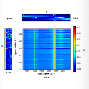
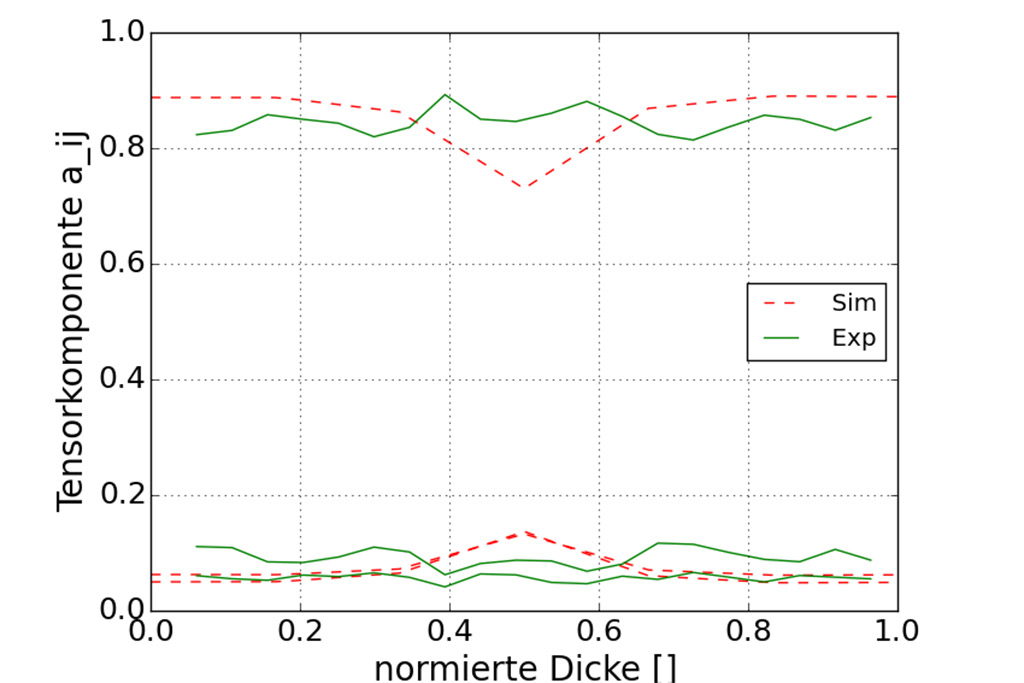
As shown in Figure 3, the fiber orientation of the UD test specimen was determined experimentally using microcomputer tomography (µCT) and compared with the simulation results. The determination of fiber orientation based on µCT data was carried out using GF-DETECT software developed at Fraunhofer LBF, the mode of operation of which is explained in greater detail in [3]. The software was further developed within the scope of the project. This meant that the process parallelization was able to be optimized and the analysis process was able to be accelerated many times over through the most modern hardware.
The aim of attaining homogeneous fiber orientation in the test area across the board thickness has been achieved. It is between 81% and 88%. This means that, for example, 88% of the fibers in the corresponding measuring point are facing in the spraying direction.
Shrinkage and warping simulation
As part of the research project, a method was developed which allows the shrinkage and warping simulation to be carried out in the Finite Elements Solver ANSYS®. This procedure offers significantly improved options for the optimization of warping simulation compared to established procedures in which the results are determined directly within the process simulation and transferred to the structural simulation. For this purpose, the status information (local temperatures and pressures) of the polymer from the injection molding simulation are transferred to ANSYS® and the component shrinkage and warping are calculated there. The observation of shrinkage and warping in the structural simulation environment disconnected from the injection molding simulation allows for a significantly more detailed testing of the constituent framework conditions.
This approach offers the advantage that the material behavior which is described by material models can be adapted in a very flexible manner. Alongside a variety of material models which have already been implemented, such as those to describe the viscoelastic material behavior, dedicated models may be implemented in the solvers. Results from the shrinkage simulation, such as component deformation or internal stress, may continue to be used directly in a subsequent simulation, e.g. for testing the component behavior under strain. Likewise, it is possible to represent framework conditions, such as the time-dependent affixing of the component in the cavity or free shrinkage following deformation.
The procedure described is suitable for both non-reinforced and reinforced polymers. Alongside the state variables of the plastic, the calculated fiber orientation can also be transferred and the resulting anisotropic properties taken into account.
The test specimens newly developed at Fraunhofer LBF and the methods presented for the warping simulation provide procedures which can be used for a more precise design of plastics. Through the new test specimens, the inadequacies of variants which were previously available can be avoided. A higher level of prognostic certainty allows for high quality products and enables the available lightweighting potential to be harnessed.

“The newly developed test specimen offers exciting new possibilities for the determination of the threshold material behavior and thus makes a significant contribution to the safe design of short fiber-reinforced plastic components.” Markus Fornoff, M. Eng.
Literature
[1] M. Stommel, M. Stojek, W. Korte: FEM zur Berechnung von Kunststoff- und Elastomerbauteilen. [FEM for the calculation of plastic and elastomer components.] Carl Hanser Verlag, Munich, (2nd edition), pg. 106 et seq. (2018)
[2] R. Hegler: Struktur und mechanische Eigenschaften glaspartikelgefüllter Thermoplaste. [Structure and mechanical components of glass particle-filled thermoplastics] Dissertation, Technische Hochschule Darmstadt, Darmstadt (1987)
[3] R. Gloeckner, S. Kolling, C. Heiliger: A Monte-Carlo Algorithm for 3D Fiber Detection from Microcomputer Tomography. Journal of Computational Engineering, vol 2016, Article ID 2753187, 9 pages (2016)
Contact
- Markus Fornoff, M. Eng.
- Phone: +49 6151 705-8019
- markus.fornoff@lbf.fraunhofer.de
- Tamara van Roo, M. Eng.
- Phone: +49 6151 705-8994
- tamara.van.roo@lbf.fraunhofer.de